 Türkçe
 Deutsch
 العربية
 Azərbaycanca
 Русский
 Ελληνικά
 Español
 Français
Electronic Connections and Circuits in an Electric Bağlama
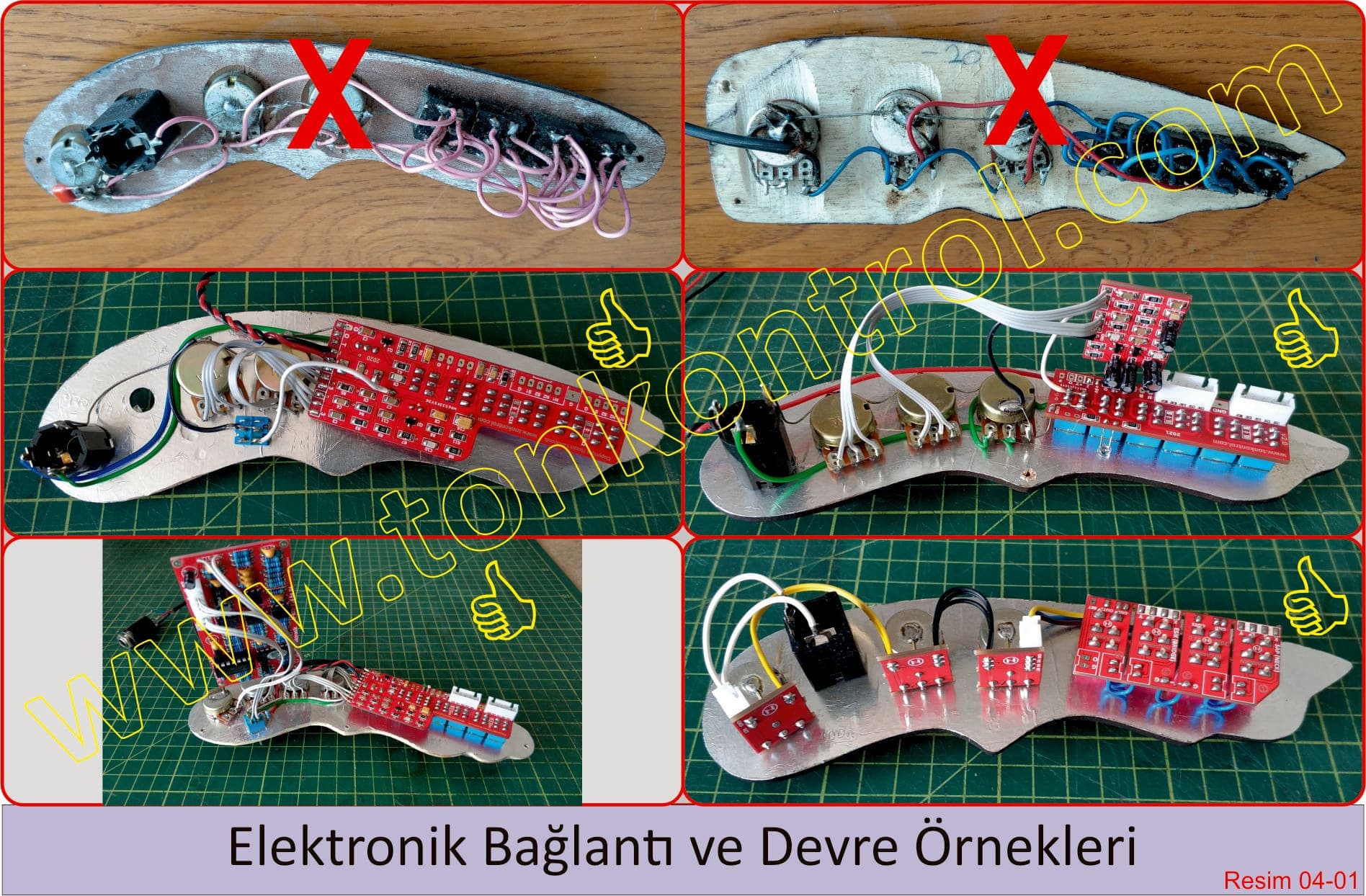
The factors that shape an electric bağlama's tone most are the electronic connections inside the instrument, the electronic circuits and the electronic components used. The picture below shows good and bad examples of connections.
The sound signals that pickups convert into varying electrical signals have to be shaped by different electronic components and connection methods, then passed to amplifying systems (preamp, amp, mixer, etc.) to become audible. The systems musicians call "tone circuits" come in many designs and do exactly this job.
Two types of tone circuit are commonly used in electric bağlamas.
Passive tone control circuit: The electrical signals generated by the pickups pass through switching, level control and passive filtering before reaching the amplifying devices. No amplification is applied to the signal, and the electronic components used cause a slight drop from the original signal level. When these circuits are used with large sound systems, the signal level can be too low, and signal boosting (a pedal, processor, etc.) is needed between the circuit and the system. In small portable amps known as çanta anfi, the signal weakness is felt less or not at all, because their preamp circuits are usually stronger.
Active tone control circuit: The electrical signals generated by the pickups pass through switching, level control, active filtering and preamplification before reaching the amplifying devices. The signals from the pickups are filtered and preamplified before being sent to the output. When these circuits are used with large sound systems, there is no signal level shortfall, and no extra systems such as pedals or processors need to be placed in between to make up for weak signal.
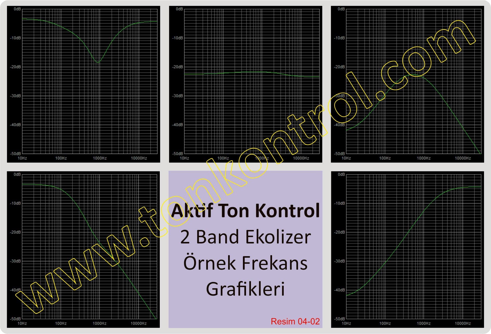
Tone control systems have many technical details that could be explained at length, but rather than burying musicians in them, it is best to list the key points that people without a technical background should watch for. An ideal tone control system should be built with attention to the following points.
- Always use high-quality electronic components with the correct values. The quality and grade of the switches and the level-control parts (potentiometers) matter a great deal in the circuit.
- Keep wiring on the circuit to the lowest possible level, and make connections with printed circuit boards (PCB) rather than loose wires.
- For the wires in the circuit, high-quality multi-strand copper wire is preferred. Single-strand wire (like doorbell wire) must never be used for wiring.
- Avoid splicing pickup cables. If they need replacing, replace them with a single, unspliced cable in place of the original.
- Always use high-quality shielded (coaxial) cable between the circuit and the output jack.
- The grounding lugs of all passive components used in the circuit (switches, potentiometers, jacks, etc.) should be joined with high-quality multi-strand copper ground wire, and this connection should be made to the circuit's common ground.
- The back surface of the wooden part the circuit is mounted on should be fully covered with aluminum or copper foil to form a common ground.
- If an active preamp circuit is used, make sure it is properly designed, uses quality components, and is preferably built on a double-layer PCB with a common ground.
- All soldering on the circuit should be done properly and to a high standard. There should be no faulty joints, known as cold solder joints.
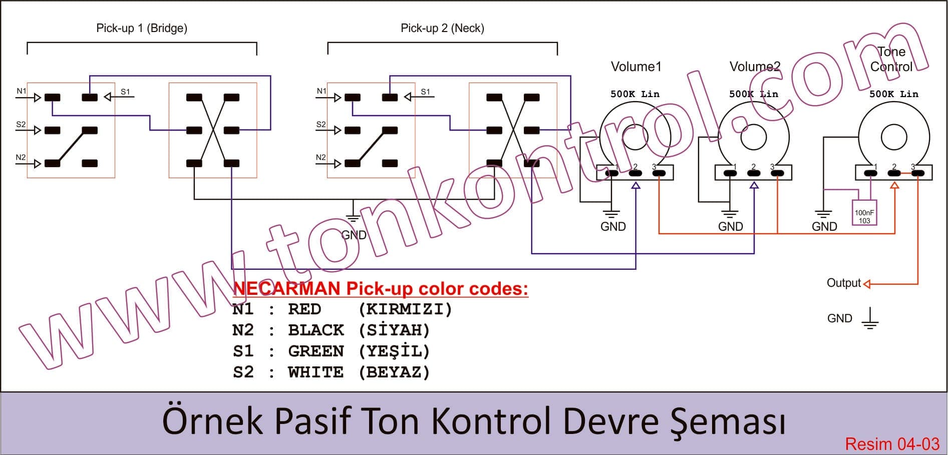
Finally, for those interested, here is a passive tone control circuit diagram (with Necarman pickup color coding).